Professional, Familiar DWG‐based 2D & 3D CAD for Mechanical Design and Drafting.
Without Compromise
Fastest Path to Production
Start with any design data, add details and then quickly generate complete and accurate production materials.
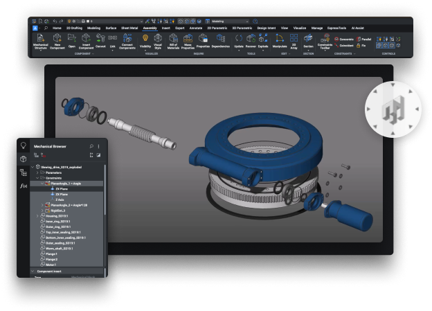
BricsCAD Mechanical is a powerful tool designed for engineers and designers who work with 3D mechanical design and manufacturing processes. It is built on the DWG platform, providing a familiar environment for CAD users while offering advanced mechanical design capabilities. BricsCAD Mechanical combines parametric modeling, sheet metal design, assembly management and more into a single, comprehensive solution.

BricsCAD Mechanical makes advanced mechanical design accessible, intelligent, flexible and affordable, enabling greater design freedom. BricsCAD’s unique variational 3D modeling approach gives you the freedom to design how you want to, from concept to detail, with whatever level of parametric control you need. Quickly develop complex stand-alone components or directly within an assembly.
With BricsCAD Mechanical, the design process is simple. Compose assemblies as top-down or bottom-up designs. Start your design with a 2D sketch, then extrude, revolve, or sweep it to create a 3D solid. You can also use built-in 3D primitives to specify the initial shape of your part. Move on to the details using extrusions, fillets, chamfers, Boolean operations and edit using dynamic direct modeling. You control as much or as little of the form as you like with parameters. You can also import 3D solids and edit them as native components.
The software offers the best and most familiar workflow for turning your mechanical designs into production drawings. Automatically create drawing views of your 3D parts and assemblies and detail views easily with dimensions and annotations. If your 3D model changes, generated drawing views are updated automatically.
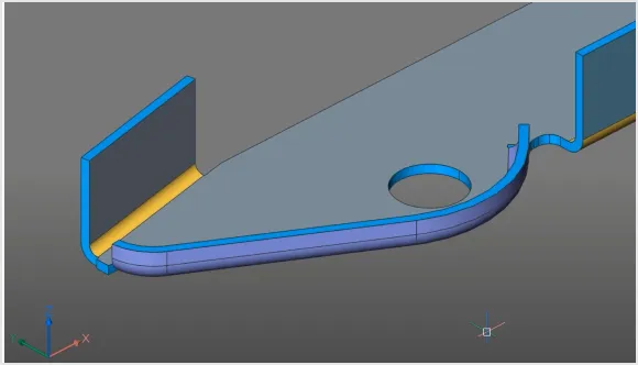
Create sheet metal part designs that are resilient and deeply editable. BricsCAD Mechanical can create sheet metal components from scratch and allows users to automatically convert solid parts to sheet metal with just one click. This robust approach lets you spend more time evolving your design and less time worrying about redefining sheet metal features.
Sheet metal parts can be edited with the full power and freedom of direct modeling, while the consistency of each feature (flanges, bends, reliefs, junctions) is automatically maintained.
Create un-folded 2D representations that are bi-directionally associated to the 3D sheet metal part. You can also use the unfolding engine to send parts to industry-standard CAM systems.
Bring CAD data from many other formats seamlessly into BricsCAD with Communicator for BricsCAD. Easily and quickly build it into your assemblies, modify it via direct modeling, or make it intelligent by applying parameters.

BricsCAD Mechanical allows users to work with both direct modeling and parametric design. This flexibility enables users to create and modify 3D models intuitively, adapting to design changes quickly.
The software supports the creation and management of complex assemblies. Users can work with components, sub-assemblies and full assembly structures, making it ideal for designing mechanical systems with multiple connecting parts.
Users can apply 3D constraints to maintain relationships between parts, ensuring that changes to one part automatically update connected components, preserving design intent and accuracy.

BricsCAD Mechanical offers a cost-effective alternative to other mechanical design software, providing powerful features at a competitive price point, making it accessible to businesses of all sizes. An economical alternative to costly and excessively complex history-based solid modellers.
The software provides flexible licensing options, including perpetual licenses and subscription models, allowing organizations to choose the best solution for their needs and scale as their projects grow. Licenses do not require named users, supporting both full-time and occasional use, and have no geographical restrictions - one licence for planet Earth.

BricsCAD Mechanical offers robust sheet metal design tools, enabling users to create sheet metal parts with ease. This includes features like flanges, bends, junctions and corner reliefs.
The software automatically unfolds sheet metal parts to create flat patterns for manufacturing, saving time and reducing errors in production.
Users can define custom bend tables and K-factors to ensure that sheet metal designs meet specific manufacturing standards and requirements.

BricsCAD Mechanical supports hierarchical assembly structures, allowing users to organize components and subassemblies logically. This facilitates better management of complex projects.
The software enables the creation of exploded views of assemblies, which are essential for assembly instructions, documentation and presentations.
BricsCAD Mechanical can generate Bills of Materials (BOM) automatically from assemblies, streamlining the documentation process and ensuring accuracy in parts lists.

Built on the DWG platform, BricsCAD Mechanical ensures compatibility with other CAD systems, making it easy to share and collaborate with users across different platforms.
The software includes a library of standard parts and components, such as fasteners, gears and bearings, which conform to industry standards. This helps accelerate design processes and ensures compliance with standards.

BricsCAD Mechanical integrates 2D drafting and 3D modeling in a single environment, allowing users to switch between 2D and 3D seamlessly. This reduces the need for multiple software tools and enhances productivity.
Users can convert 2D sketches and drawings into 3D models effortlessly, enabling quick transition from conceptual designs to be detailed 3D representations.
The software supports associative 2D drawings, meaning changes made to the 3D model automatically update the corresponding 2D documentation, ensuring consistency and reducing errors.
BricsCAD Mechanical supports customization through Lisp and APIs, allowing users to automate repetitive tasks, create custom commands and tailor the software to meet specific needs.
Users can create parametric components with customizable parameters, making it easy to adapt designs for different configurations and requirements.
The software includes automation tools that streamline design processes, such as the Propagate tool, which intelligently replicates design features across similar geometry.

BricsCAD Mechanical integrates with cloud-based collaboration platforms like Bricsys 24/7, enabling team members to access project files from anywhere and collaborate in real-time.
When used with Bricsys 24/7, the software supports a multi-user environment, allowing multiple users to work on the same project simultaneously, enhancing collaboration and speeding up project delivery.
BricsCAD Mechanical is available on Windows, macOS and Linux, providing flexibility and accessibility for users across different operating systems.

BricsCAD Mechanical offers realistic rendering capabilities, allowing users to create photorealistic images and animations of their designs for presentations and client reviews.
The software provides advanced visualization tools, including section views, dynamic cross-sections and exploded views, which aid in understanding complex assemblies and designs.
BricsCAD Mechanical integrates with virtual reality tools, providing immersive experiences that enhance the understanding and communication of design intent.

Users have access to a variety of training resources, including tutorials, webinars and documentation, to help them fully leverage the capabilities of BricsCAD Mechanical and stay up to date with the latest features.
Bricsys offers extensive technical support to assist users with troubleshooting, software updates and best practices, ensuring smooth operation and maximizing productivity.
Bricsys fosters a strong user community, providing forums and user groups where professionals can share insights, ask questions and collaborate on best practices.
BricsCAD Mechanical software is a powerful and flexible solution for engineers and designers involved in mechanical design and manufacturing. Its comprehensive modeling capabilities, integrated workflow and support for industry standards making it an invaluable tool for enhancing productivity, collaboration and design quality. By using BricsCAD Mechanical, teams can streamline their workflows, reduce risks and deliver high-quality solutions efficiently, ultimately contributing to the success of their projects.

BricsCAD’s unique variational 3D modeling approach gives you the freedom to design how you want to, from concept to detail, with whatever level of parametric control you need. Quickly develop complex stand-alone components or directly within an assembly.

With BricsCAD Mechanical, the design process is simple. Start your design with a 2D sketch, then extrude, revolve, or sweep it to create a 3D solid. You can also use built-in 3D primitives to specify the initial shape of your part. Move on to the details using extrusions, fillets, chamfers, Boolean operations and edit using dynamic direct modeling. You control as much or as little of the form as you like with parameters. You can also import 3D solids and edit them as native components.
Our unique 3D design approach combines dynamic and interactive direct modeling with the ability to add parameters only where needed and without the complexity of a history-based approach.

The PARAMETRIZE AI workflow turns parts into smart, parameter-driven components in seconds. Build constraint systems, drive parts formulaically, build table-driven components and change component parameters in the BricsCAD Properties Panel.

Model features once and use them many times with powerful tools that copy existing features in 3D solids such as holes, ribs and pockets.

BricsCAD contains a library of standard hole features – you can easily insert holes into your parts via drag and drop actions.
3D COPYGUIDED automatically aligns copied sets of features to relevant geometry using automatically generated guide curves. You can explicitly select entities to use as guide curves or let BricsCAD determine them based on the drawing elements in your selection.

Create rigid pipework, then add parametric valves, flanges and associated fastenings. All from a comprehensive library of items, which intelligently resize correctly via a one-click process.
Create sheet metal part designs that are resilient and deeply editable.

BricsCAD Mechanical can create sheet metal components from scratch and allows users to automatically convert solid parts to sheet metal with just one click. This robust approach lets you spend more time evolving your design and less time worrying about redefining sheet metal features.
Sheet metal parts can be edited with the full power and freedom of direct modeling, while the consistency of each feature (flanges, bends, reliefs, junctions) is automatically maintained.
Create un-folded 2D representations that are bi-directionally associated to the 3D sheet metal part. You can also use the unfolding engine to send parts to industry-standard CAM systems.
The flexibility of direct modeling maintains design intent, expressed as sheet metal features – flanges, bends, reliefs and others.
3D models created in BricsCAD or other CAD systems can be converted to sheet metal automatically, with one click. Features can then be manually refined or changed to quickly achieve your desired form.

Create 2D and 3D unfolded representations to drive CAM systems. The 3D unfolded representation can be edited simultaneously to fix detected conflicts, while keeping the 3D folded part in sync.

Use the full power of 3D constraints, arrays and automatic parametrization to create different design variants from your sheet metal models.

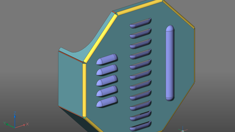
The hem feature for Sheet Metal allows you to model a hemming metal-working process. BricsCAD supports open hems, teardrops and rounds with user-adjustable parameters.
BricsCAD Mechanical provides a library of parametric form features – such as louvers, bridges, embosses and others. You can also create complex ribs defined by any curve.

You can create lofted sheet metal parts between two arbitrary 3D curves. BricsCAD Mechanical can recognize lofted bends in imported geometry and automatically decompose them into multiple flanges.
Create flanges in multiple ways: using a base flange, an edge flange or a via a contour tool. You can always change the way adjacent flanges connect – via a bend, a junction, or a tab-and-slot connection – to improve manufacturability.

Avoid material conflicts during the bending process by leveraging the library of reliefs in BricsCAD Mechanical. Split parts in a single click and automatically propagate the split to other corners in your model.
Build potentially complex assemblies and subassemblies using components designed in-house or by others.
BricsCAD Mechanical users can create complex hierarchies of parts and sub-assemblies using bottom-up or top-down design methods. You can import assemblies from different CAD systems using Communicator for BricsCAD, including Parametric geometry defined in those assemblies.


BricsCAD offers the best and most familiar workflow for turning your mechanical designs into production drawings.

Automatically create drawing views of your 3D parts and assemblies and detail views easily with dimensions and annotations. If your 3D model changes, generated drawing views are updated automatically.

Speed up drawing layout using fast, draft-quality views and use multi-core CPUs to create detailed views in record time. BricsCAD Mechanical is responsive to your inputs during background drawing generation.
Automatic drawing update Drawing views remain associated with the 3D model. Change a single part, subassembly, or the whole assembly and all 2D drawing views are automatically updated, allowing fast design iterations and changes.

You can create section views of 3D parts and assemblies. Section planes can be defined by a line drawn on a base view, or you can create more complex sections: half sections, offset sections and aligned section views.

BricsCAD Mechanical allows you to automatically create detail views from any existing view in your drawing layout.
The BOM panel lets you manage multiple BOM tables in your drawings. You can format each column individually, set up equations, sort tables and more.

BricsCAD Mechanical creates associative balloons for each component in an assembly and manages the display of those tags in all automatically generated 2D views.

All the 2D detailing annotations you need, from datums and geometric tolerances to surface finishes to weld symbols and representations, are available at your fingertips to quickly create 2D production drawings.

The POWERDIM tool intelligently creates the right dimension for the selected geometry, including fits and tolerances, making dimensioning your drawing views effortless.

Easily open, edit and reuse symbols and annotations in your drawings created in AutoCAD Mechanical.
Bring CAD data from many other formats seamlessly into BricsCAD with Communicator for BricsCAD. Easily and quickly build it into your assemblies, modify it via direct modeling, or make it intelligent by applying parameters.
“BricsCAD Mechanical contains all the tools I need as a machine builder: sheet metal, support for 2D drawing and 3D modeling, various materials. Moreover, everything works in DWG”
“BricsCAD is an excellent tool to work with. When we send parts off for manufacture, the manufacturer has not yet had any problems opening the BricsCAD files we have provided.”
“BricsCAD Mechanical has enabled our team to set even higher standards for structural and mechanical drawings”