.webp)
CAESAR II evaluates the structural responses and stresses of piping systems to international codes and standards. CAESAR II is the pipe stress analysis industry standard against which all others are measured.
CAESAR II enables quick and accurate analysis of piping systems subjected to a wide variety of loads (including weight, pressure, thermal, seismic, and other static and dynamic conditions) following more than thirty-eight international piping code standards, and many environmental and equipment guidelines.

CAESAR II is used for a variety of reasons, but mainly because Owner operators mandate its use to check that the piping designed for their facility after it is commissioned and operational is going to be operate reliably and safely. CAESAR II is usually mandated due to its maturity, calculation accuracy, and ability to cater to the analysis requirements of many different projects in many industries, ensuring piping is certified in accordance with the design codes and standards that apply wherever an industrial facility resides in the world.

CAESAR II is a renowned software application for pipe stress analysis. Extensively used by engineers and designers to evaluate the structural response of piping systems to various loads and ensure their safety, compliance, and reliability.
EPC companies and Owner operators worldwide use CAESAR II for analysis of piping systems found in their offshore and onshore projects.


Software internationally recognised by EPCs, Owner operators, and Notified Bodies.

CAESAR II allows users to perform both static and dynamic stress analyses, accommodating a wide range of load conditions, including thermal expansion, pressure, seismic, wind, and other dynamic forces. This comprehensive approach ensures that all critical aspects of piping stress are evaluated.
The software supports nonlinear analysis, accounting for large displacements, nonlinear restraints, and other complex behaviours in piping systems. This capability allows for more accurate modelling of real-world conditions.

CAESAR II supports a variety of international piping codes and standards, including ASME, ISO, EN, B31.1, B31.3, and many others. This ensures that designs meet regulatory and safety requirements specific to different regions and industries.
The software automatically checks for code compliance, providing engineers with insights into stress levels, allowable limits, and potential areas of concern.

CAESAR II features a user-friendly interface that simplifies the modelling process. Engineers can quickly create models using graphical input, reducing the learning curve, and increasing efficiency.
The software provides 3D visualization capabilities, allowing users to view and interact with piping models. This visual representation aids in understanding complex piping configurations and identifying potential issues. Evaluation of stress analysis results is made easier though cutting-edge graphics that are highly responsive and performant during model creation, manipulation, and viewing. Graphical animation of results aids decision making and problem resolution.

CAESAR II enables the modelling of various load types, including thermal, pressure, dead weight, live load, and occasional loads. Users can define load cases and combinations to simulate real-world conditions accurately. Comprehensive definition of load cases supported by a dedicated editor, ensuring all conditions that the piping is subject to, are considered and evaluated.
The software offers a wide range of support and restraint types, including spring hangers, snubbers, and anchors. Engineers can model these elements to reflect actual support conditions and optimize the design.
CAESAR II integrates seamlessly with other Hexagon products facilitating data exchange and collaboration across disciplines. Bi-directional integration with CADWorx Plant Professional reduces risk of errors and costly iteration time between plant piping design and stress analysis disciplines, enhancing workflow efficiency and reducing data duplication.
The software supports data import and export from various CAD and engineering software, allowing for easy data transfer and collaboration with other teams and stakeholders. An Advanced PCF interface supports import of piping models from a variety of piping and plant design systems.
Possible via CIMSTEEL CIS/2 or GT STRUDL .GTI, enables sharing of load details, post-analysis, ensures pipe stress analysis and civil/structural groups work together without duplicating information and effort.

CAESAR II generates detailed reports that include stress analysis results, load cases, deflection, restraint forces, and other critical data. These reports are essential for documentation, review, and compliance verification.
Users can customize report formats and output to meet specific project or client requirements, ensuring clear communication of analysis results.

Engineers can perform iterative design analysis to optimize piping systems for cost, weight, and performance. By adjusting parameters and rerunning analyses, users can find the most efficient design solutions. An in-built Loop wizard tool automates and optimises expansion loop designs saving time and material cost.
CAESAR II allows for vibration analysis, helping engineers understand how changes in parameters affect system behaviour and identifying critical factors in design decisions.
The software models accurately temperature and pressure effects on piping systems, accounting for thermal expansion, contraction, and stress due to pressure fluctuations.
CAESAR II can evaluate vibration effects and fatigue life, helping to prevent failures due to cyclic loading and dynamic forces.
Reduce piping design and analysis time, and more importantly, construction and lifecycle maintenance costs.
Load flange data for analysis of equipment connections in accordance with EN-1591 and other standards.
Analysis can only be performed when piping models and data are completely and accurately defined, otherwise CAESAR II reports errors appropriately indicating what’s missing and needs to be corrected before analysis can continue.

CAESAR II includes extensive material libraries with data on material properties, including temperature-dependent properties. Engineers can select appropriate materials for their designs or define custom materials if needed.
The software considers creep effects in materials, particularly for high-temperature applications, ensuring long-term reliability and safety.

CAESAR II is widely used in the oil and gas industry for designing and analysing complex piping systems in refineries, petrochemical plants, and offshore platforms.
The software is essential for analysing piping systems in power plants, ensuring safe operation under high-pressure and high-temperature conditions.
CAESAR II supports the analysis of piping systems in chemical plants, pharmaceutical facilities, and other process industries, where safety and reliability are paramount.

Rigorous quality assurance program complying with ASME NQA-1 quality assurance, mandatory in the nuclear industry.

Hexagon provides comprehensive technical support to assist users with troubleshooting, software updates, and best practices, ensuring that teams can fully leverage the software's capabilities.
Users have access to a variety of training resources, including webinars, tutorials, and documentation, to help them maximize the benefits of CAESAR II. Free eLearning available via Hexagon University.
CAESAR II offers a robust set of features and benefits for pipe stress analysis, making it an invaluable tool for engineers and designers in various industries. Its capabilities in analysing static and dynamic loads, ensuring code compliance, and optimizing designs contribute to safer, more efficient, and reliable piping systems.

The addition of an expansion loop is a common solution for addressing high stress or high loads in a piping system. CAESAR II offers tools to determine the most suitable location for the loop and to calculate the necessary size. CAESAR II can use a CAD model to quickly identify a suitable location for the loop, reducing the need for repeated analysis and design. The Loop Wizard can automatically design the expansion loop based on the target value and available space.
The EN-1591 standard is a calculation method for bolted, gasketed, circular flange joints that ensures structural integrity and leak tightness. It is a detailed and modern standard that provides greater accuracy than the Taylor Forge method, allowing for significant reduction in flange thicknesses and bolt sizes by up to 50% or more.
Including an expansion joint in a piping analysis model can be challenging. The user must carefully define not only the joint itself, but also any necessary tie-bars and ensure that everything is connected correctly to allow for the appropriate degrees of freedom. The correct flexibilities of the joint must also be specified from the manufacturer's catalogue. CAESAR II's Expansion Joint Modeller simplifies this process by automatically creating the model with the correct flexibilities and connections, including tie bars.
Spring hangers are crucial to supporting a piping system when balancing vertical displacements. CAESAR II allows users to select from thirty-eight hanger manufacturer catalogues to support their piping system and balance vertical displacements. CAESAR II will then select the appropriate hanger based on the load and movement at the hanger location, as specified by the user.
Piping systems in earthquake-prone areas must be designed to withstand seismic loads. Fortunately, allowing users to easily apply mapped accelerations to their models as appropriately adjusted uniform g-loads and using the Static Seismic method, in CAESAR II, This process can be completed with minimal inputs, and in seconds.
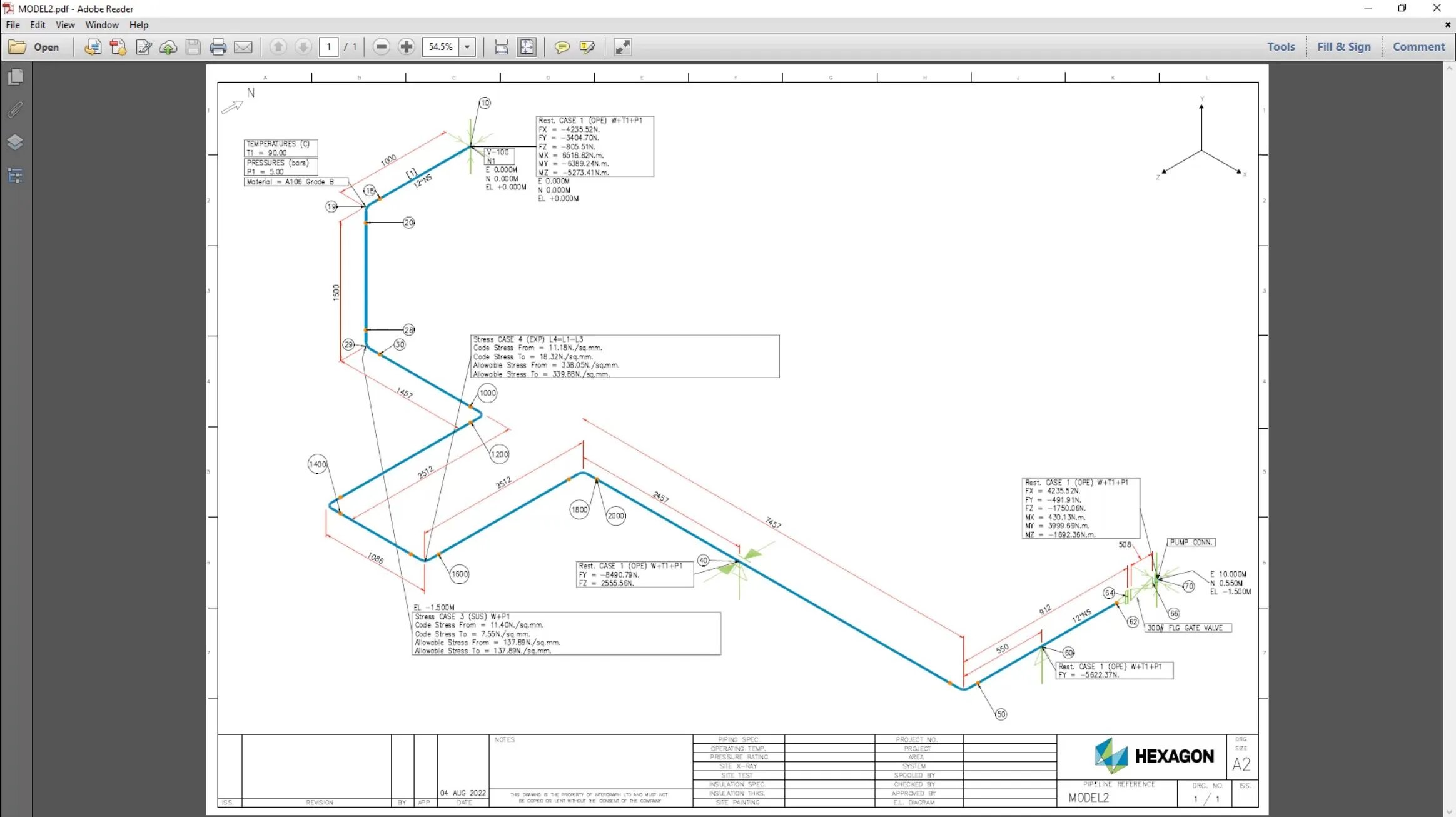
A stress isometric is a useful addition to any report, but manually annotating it can be time-consuming and prone to error. Using Isogen, an integral part of CAESAR II, accurate isometric drawings can be easily and quickly produced with just a few clicks. Simply specify the desired information and Isogen does the rest, eliminating the potential for mistakes whilst saving time.
The natural frequencies for a piping system should be calculated to reduce the risk of vibration issues, which may cause fatigue failures. A first natural frequency that is too low can mean that the pipe is easily excited and so more susceptible to vibration. Best practises indicate a recommended lowest natural frequency of no less than 4 to 5 Hz. Similarly, a natural frequency of a piping system that is close to the frequency of e.g. reciprocating equipment can also cause issues and may lead to resonance and failure. CAESAR II provides modal analysis to calculate the natural frequencies and associated mode shapes of a piping system. Running the modal analysis and reviewing the natural frequencies and the animations associated with the mode shapes is easily achieved using CAESAR II.
The process of creating a pipe stress analysis model can be time-consuming for analysts, as it often involves manually reconstructing the model from isometrics. CADWorx and CAESAR II can streamline the process by digitally transferring piping data from the design model to create the analysis model. Properties for analysis can also be transferred from CADWorx to CAESAR II, saving time and effort for the analyst. The process can also be streamlined for modifications by referencing the design model in the analysis environment and conveying changes back to the designer by importing the CAESAR II model into CADWorx. This ensures that piping finally issued for construction, matches what was analysed.
The most tedious part of conducting pipe stress analysis is often creating the model, which typically involves manually reconstructing it from isometrics. The process can be simplified by digitally transferring data from the design model in Smart 3D to CAESAR II, creating the analysis model directly. This not only saves time and effort for the analyst, but also allows for easy modifications. The analyst can reference the design model in the analysis environment, making informed decisions about changes and reducing back and forth with the designer. After the analysis is complete, the updated pipe route and support locations and loadings can be easily transferred to the designer.